Informations
Description
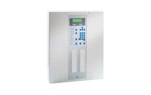
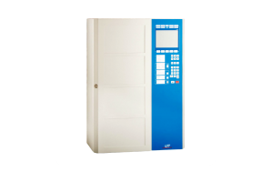
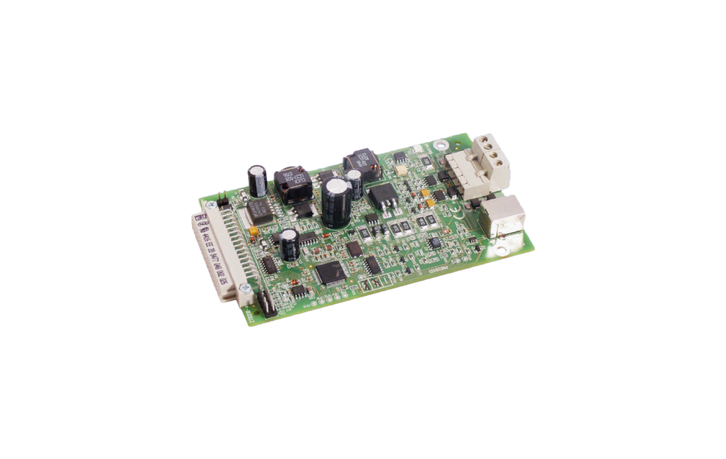
By means of the Loop Interface LIF128-1, one ADM loop with bi-directional data exchange can be connected to Fire Detection Control Panels Series BC216. The loop protocol can be parameterised on the control panel, which makes the use of different brands of detectors possible.
Up to
- 318 elements with System Sensor/200 protocol – 159 detectors and 159 modules – or
- 126 elements with Apollo/Discovery protocol or
- 240 elements with Labor Strauss/700 protocol can be connected to a single ADM loop. Thanks to the high maximum output current of 500mA, a larger number of loop elements with higher current demand – such as loop sounders – can also be used on the ADM loop.
Each ADM loop can be subdivided into a maximum of 144 detector zones. The function of the detector zone
– for example, manual call point zone, automatic fire detector zone, technical message or fault detection zone
– as well as the element types of the loop elements can be parameterised on the fire detection control panel.
The two loop connections of the loop interface – which correspond to start and end of the loop – are equipped with an isolator each. In the event of a short circuit, the isolator interrupts the loop. By means of an integrated measuring and analysis function, electrical characteristics on the loop can be obtained and faults in the loop communication can be evaluated. In the course of commissioning or maintenance, this function allows the evaluation of the transmission quality on the loop as well as the detection of external voltages, poor wiring, or of exceeding line resistances.
For this,
- the resistance of both loop lines,
- the loop current,
- the loop voltage at both terminals, as well as
- the number of faulty queries on the loop can be indicated on the Fire Detection Control Panel Series BC216 since firmware version Vx.22.
On the control panel, you can perform a maintenance prognosis for each connected smoke detector. The continuous monitoring of the detector function allows trouble-free operation and timely recognition of detector contamination.
The loop interface is equipped with a processor of its own. At a possible central processing board failure, the diversified redundancy concept thus ensures reliable alarm recognition. The firmware of the loop interface can be updated via an integrated USB interface.
Usually, the loop wiring is realised as ring. Thanks to the ring-shaped wiring, all elements on the loop keep working in the event of a single wire breakage. If necessary, branch lines can also be connected to the ring. In the event of a short circuit, the functioning of the loop elements that are cut off from the faulty loop segment by means of isolators, can be maintained. The control panel indicates a wire breakage or a short circuit as loop fault.
Unshielded wires can be used for the fire detector cabling and, therefore, existing installations can be adopted very easily and existing cabling can be reused.
Technical specifications
- Current consumption at 24V (without detectors/modules): typ. 25mA
- Number of detector zones: max. 144
- Number of detectors/modules:
- System Sensor/200 protocol max. 318 elements (159 detectors + 159 modules)
- Apollo/Discovery protocol max. 126 elements
- Labor Strauss/700 protocol max. 240 elements
- Idle loop current: typ. 300µA per detector/module
- Total loop current: max. 500mA (at reduced line resistance)
- Idle loop voltage:
- System Sensor/200 protocol typ. 29V
- Apollo/Discovery protocol typ. 26V
- Labor Strauss/700 protocol typ. 29V
- Loop line resistance: max. 50Ω per core
- Ambient temperature: -5°C to +50°C
- Dimensions L × W × H: 132 × 74 × 23 (mm)
- Weight: 80g